I'm almost one year into my time here at UIC. I've been making steady progress on my research and have run into a strange issue. My research focus is developing a new technique to make surface maps, like the one on the right, of battery cathode materials using X-ray diffraction. The material studied in this post is \(MgMn_2O_4\). By creating these maps, I am able to look for areas where the electrochemistry is different from the rest of the material. The map at the right looked promising at first; however as described below this excitement may have been premature.

Map of discharged \(MgMn_2O_4\) battery cathode based on area of 18° peak.
Mapping
Each spot on the map represents one X-ray diffraction scan. The whole map is of a ½" diameter cathode that was recovered from a magnesium coin cell after being discharged. The diffractograms below show the average over all the scans in a map. The areas highlighted in blue and green represent the 2θ ranges of the expected peaks based on the known phases. The material exists in either a discharged or charged phase, however peaks were seen that don't correspond to either phase. The purpose of this experiment was the try and learn more about their origin. The peak in the 18° range is the one I focused on here. The color of each map pixel is determined by the integrated area under this peak after background subtraction. Looking at the diffractograms from individual pixels we see that indeed the peak is strong in areas colored green and not present in areas colored blue. However, the other peaks associated with this phase do not change proportionally, contrary to the usual behavior of XRD patterns. The fact that the color scale bar on the maps does not go to zero is mostly due to low-quality background fitting in some pixels.

Average of diffractograms from each scan in original map (blue) and map after 180° rotation of sample (green).
Sample Rotation
Puzzled by the strange behavior of the 18° peak, I wanted to see if this was perhaps an artifact of the instrument, rather than the sample. I rotated the sample 180° and made another map. The two are shown side-by-side below. Since the sample was rotated 180°, I expected the resulting map to also be rotated. This was not the case, leading me to suspect that this effect is either due to the instrument itself or to some aspect of the sample mounting method.


Maps and reconstructed micrographs of \(MgMn_2O_4\) in original orientation (left) and after 180° rotation on specimen stage (right). Differences in spot size are due to changes made to mapping software between experiments.
The images below show how the sample was mounted. I am working at fairly low angles and the detector is set around 11° (θ-2). Because of this it is possible that the 18° peak is blocked in some areas. It is possible that the tape used to mount the specimen is obstructing the X-ray beam, though this does not appear to be the case in the photos and would require very similar obstruction upon remounting the specimen. It is also possible that the specimen itself is not perfectly flat and that some areas are obstructed by other areas of the sample. It is difficult to imagine, however, how this would result in the effect seen here; the right area would need to be blocked by something that itself doesn't contain the target peak but yet doesn't block the electrode where the 18° peak is visible (green areas). Furthermore this effect would have to be symmetrical in order to produce the same artifact after rotating the specimen.
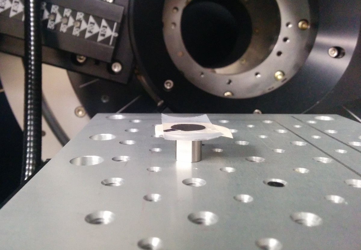
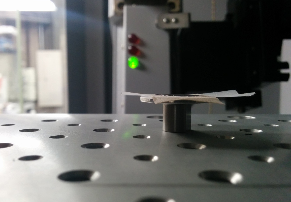
Mounting of \(MgMn_2O_4\) on µ-XRD specimen stage from front (left) and side (right).
Ultimately, I don't know the source of this artifact; I may need to run more experiments to test some ideas. Regardless of the outcome, I intend to come up with a better way of mounting specimens to replace the multiple layers of tape I'm currently using. I will also be on the look-out for this effect in future work.